In all critical applications like aircrafts, medical equipment and automobiles, there is a requirement for the systems to be reliable and safe. These requirements are important since human lives are at stake, which have led to the development of safety standards in various industries. The basic idea behind functional safety is that the overall system should remain dependable, even in the event of an unplanned or unexpected occurrence. The ISO 26262: Road Vehicle Functional Safety (FuSa) standard is an international standard focusing on the safety of automotive electrical / electronic systems. The ISO standard provides recommendations from conceptual development to decommissioning of the product. The standard addresses faults resulting from Electrical/Electronic (E/E) systems malfunctioning and not due to fire, radiations, corrosions etc. These failures can be systematic failures (due to faults during development, manufacturing or maintenance) or random (during the life-time ) or malicious failures (deliberately injected).
Risk Classification
The ISO standard employs an automotive specific approach for identifying risks involved. The standard considers three factors: severity, exposure and controllability to classify risk into four Automotive Safety Integrity Levels or ASILs. Severity is the measure of the amount of harm any unexpected event can cause, whereas exposure considers the probability of occurrence of any such events and controllability is defined as the ability of the system to avoid the specified harm. This ASIL classification is an important aspect for ISO standard compliance and is identified at initial stages of development. The ASIL classification has four categories from ASIL A to D. The ASIL A is the least stringent level of safety reduction, while ASIL D is the most severe. The most critical systems like Anti-Braking system, electric steering belong to the ASIL D category, whereas rear lights are part of the ASIL A category. Based on the ASIL classifications, the safety goals/features are determined.
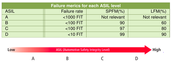
Failure rate is the rate at which the component experiences faults and it is expressed in FIT i.e. Failure In Time. The FIT rate is the number of failures expected in one billion hours of operations. As per ISO 26262, Single-point fault metric (SPFM) and Latent fault metric (LFM) can be used as the measurement of functional safety for hardware components. Failure metrics for each ASIL level is given below. SPFM and LFM are architectural metrics, which analyses whether coverage provided by safety features are sufficient to prevent failures resulting respectively from single point faults and latent (multiple point) faults.

The motivation behind safety analysis is to ensure that any deviations from safety goals results only in minimum risks to passengers. The safety analysis can be done qualitatively (identification of hazards without analysing frequency of failures) or quantitatively (identification of only random failures along with their frequency of failure). Some safety analysis techniques are listed below.
- HARA (Hazard Analysis and Risk Assessment): Evaluates all possible hazards in a system and ranks them according to severity and controllability.
- FMEA (Failure Mode and Effects Analysis): Focuses on the individual component of a system and how its failures affect the overall system.
- FMEDA (Failure Mode Effects and Diagnostic Analysis): Identifies issues early in development through detailed examination of error causes and its effect on the entire system.
In the above analysis techniques, for each failure mode, the failure rate, safety mechanisms and its coverage are analysed and combined to calculate the SPFM, the LFM, and the FIT rate. The overall metric is obtained by summing up individual entries.
In automobiles, safety practices are ensured in components like: processing units, memories, I/O interfaces, communication units, sensors and actuators, clocking, data and control paths, power supply, control sequences etc. The overall functional safety workflow constitute of
- Identifying and accessing the possible risks/failures.
- Determining methods to reduce the failure.
- Implementing functional safety features.
- Verification and validation of functional safety features.
Safety Design
The safety system design can be either redundancy or checker based designs. In redundancy, multiple processing paths are designed to limit the risk of failure. It consumes more IC area. Most redundancy mechanisms work on the MooN(M out of N) concept i.e., at least M out of N redundant path/part should be functionally correct for that component to be considered as safely working. Redundancy can be either hardware, software, information or time redundancy. In checker design, the system will be continuously monitored and once error occurs, error response will be triggered. This logic doesn’t consume much area. Some of the effective functional safety practices are listed below:
- Triple Modular Redundancy (TMR) is widely used in strict ASIL category components. Here, logic paths or registers which may get affected by possible faults are replicated thrice. If any one register fails and the other two are functioning correctly, then failure is masked by taking the two correct values. It is necessary to keep these replicas far from one another to avoid any possible interdependencies. In this method, both error detection and correction is possible.
- Similar to TMR, we have Dual Modular Redundancy, where two replicas of path/component will be present. This method is capable of error detection but not correction.
- Error Correction Code (ECC): When Flash memories get affected by errors, often read data will get corrupted. ECC is useful for error detection and correction in such scenarios.
- Cyclic Redundancy Code (CRC): Check value for all data stored in memory is calculated, that helps in error detection while reading the data.
- Lockstep Processor: The highly critical processor core is replicated and the same set of inputs is given to both the cores at the same time. A comparator logic is designed to compare outputs from cores on cycle to cycle basis. Any differences will trigger error responses.
- Delayed Lockstep Processor : Time redundancy based technique, where all inputs to one of the replicated cores is delayed by N clock cycles. The outputs of the second core are delayed by the same N cycles before comparison. This time diversity ensures that the probability of failure/noises affecting functionalities of both the cores in the same manner, is minimum.
A Case Study
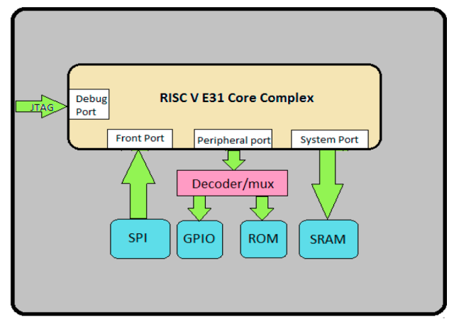
The checker and redundancy based safety mechanism had been implemented in a RISC-V based SoC. Such a safety critical system needs to have safety mechanisms everywhere. The SoC architecture diagram is given below.

In the SoC, peripherals like SRAM, ROM , GPIO and watchdog timer are interfaced to RISC-V E31 core through AMBA AHB-lite protocol. The Single error correction Hamming code was implemented across SRAM. ROM is implemented with cyclic redundancy check safety mechanism. The interrupts from GPIO come along with an interrupt redundancy support. The processor is replicated (lockstep) to ensure functional safety, which falls under hardware redundancy.
Conclusion
Functional safety is a critical aspect in automotive systems. Based on the ASIL categories, checker or redundancy based functional safety features can be implemented across various hardware components. The techniques like TMR or ECC, which provide both error detection and correction are preferred for high risk category components.
References
- International Organization for Standardization (ISO): ISO 26262. Road vehicles – Functional safety Parts 1–9 (2018)
- ”Functional Safety Methodologies for Automotive Applications” Cadence
- “Safety requirements and validation methods for safety-related automotive electronics”
- https://www.synopsys.com/implementation-and-signoff/resources/articles/fusa-mainstream.html
- https://www.cadence.com/content/dam/cadence-www/global/en_US/documents/solutions/automotive-functional-safety-wp.pdf.
This blog first appeared on Ignitarium.com.


