The use of this site and the content contained therein is governed by the Terms of Use. When you use this site you acknowledge that you have read the Terms of Use and that you accept and will be bound by the terms hereof and such terms as may be modified from time to time.
All text, graphics, audio, design and other works on the site are the copyrighted works of nasscom unless otherwise indicated. All rights reserved.
Content on the site is for personal use only and may be downloaded provided the material is kept intact and there is no violation of the copyrights, trademarks, and other proprietary rights. Any alteration of the material or use of the material contained in the site for any other purpose is a violation of the copyright of nasscom and / or its affiliates or associates or of its third-party information providers. This material cannot be copied, reproduced, republished, uploaded, posted, transmitted or distributed in any way for non-personal use without obtaining the prior permission from nasscom.
The nasscom Members login is for the reference of only registered nasscom Member Companies.
nasscom reserves the right to modify the terms of use of any service without any liability. nasscom reserves the right to take all measures necessary to prevent access to any service or termination of service if the terms of use are not complied with or are contravened or there is any violation of copyright, trademark or other proprietary right.
From time to time nasscom may supplement these terms of use with additional terms pertaining to specific content (additional terms). Such additional terms are hereby incorporated by reference into these Terms of Use.
Disclaimer
The Company information provided on the nasscom web site is as per data collected by companies. nasscom is not liable on the authenticity of such data.
nasscom has exercised due diligence in checking the correctness and authenticity of the information contained in the site, but nasscom or any of its affiliates or associates or employees shall not be in any way responsible for any loss or damage that may arise to any person from any inadvertent error in the information contained in this site. The information from or through this site is provided "as is" and all warranties express or implied of any kind, regarding any matter pertaining to any service or channel, including without limitation the implied warranties of merchantability, fitness for a particular purpose, and non-infringement are disclaimed. nasscom and its affiliates and associates shall not be liable, at any time, for any failure of performance, error, omission, interruption, deletion, defect, delay in operation or transmission, computer virus, communications line failure, theft or destruction or unauthorised access to, alteration of, or use of information contained on the site. No representations, warranties or guarantees whatsoever are made as to the accuracy, adequacy, reliability, completeness, suitability or applicability of the information to a particular situation.
nasscom or its affiliates or associates or its employees do not provide any judgments or warranty in respect of the authenticity or correctness of the content of other services or sites to which links are provided. A link to another service or site is not an endorsement of any products or services on such site or the site.
The content provided is for information purposes alone and does not substitute for specific advice whether investment, legal, taxation or otherwise. nasscom disclaims all liability for damages caused by use of content on the site.
All responsibility and liability for any damages caused by downloading of any data is disclaimed.
nasscom reserves the right to modify, suspend / cancel, or discontinue any or all sections, or service at any time without notice.
For any grievances under the Information Technology Act 2000, please get in touch with Grievance Officer, Mr. Anirban Mandal at data-query@nasscom.in.
By enabling interoperability, EV Charging standards ensure that EV owners can charge their cars from any compatible EV Charger. The IEC 61851 standard defines Analog Signalling that ensures electrical safety and facilitates basic communication between the EV Charger and the car. Basic communication includes features such as plug-in detection and readiness to charge. The Combined Charging System 2 includes real-time digital communication over Power Line Communication (PLC), also known as High-Level Communication, which is defined by the ISO 15118 standard. This forms a complete e-Mobility communication system for EV Charging. It ensures that the charging requirements, capabilities and limitations of both the EV Charger and the car are understood and synchronized throughout the charging session. During the charging session, the EV Charger communicates with the car using High-Level Communication. This enables the EV Charger to pass information about the car to the backend Charging Management Software (CMS) over the Open Charge Point Protocol (OCPP).
Introduction
How does an EV Charger know how much energy to pump into a car battery? How does it know that the battery is flat currently so it needs to be charged at maximum current? How does the EV Charger know the time of departure desired by the user? And how does it correctly display the remaining time to charge?
Recap
Welcome back to the world of EVSE-EV communications. In the previous (first) part of this article, we discussed the 2 types of communication between the EV Charger and the car. In the Combined Charging 2 system, these are:
1. Analog Signalling (AS), defined by the IEC 61851 standard (the successor of the US SAE J1772)
2. High-Level Communication (HLC), defined by the ISO 15118 standard (the successor of the German DIN SPEC 70121)
In the previous (first) part, we had deep-dived into AS. In this (second) part, we take a closer look at how HLC works, and how it is related to AS.
Why HLC?
So, if AS already serves the purpose of handshaking between the EV Charger and the car regarding plug in events, the readiness for charging and negotiation of charging current for the session, then why is HLC required? Are there any features provided by HLC over and above AS?
The short answer is Yes. HLC enables enhanced features, like the exchange of charging parameters between the car and the EV Charger. Like the requested energy and charging current, as well as information like the state of charge (SoC) of the battery, remaining time to charge etc. It also opens up the possibility for the Charging Operator to operate a Cloud-based (*) billing and payment system that is critical for public charging infrastructure.
(*) Cloud — Most modern EV Chargers are connected to the Cloud, where a Charging Management Software (CMS), that is owned and operated by the Charging Operator, provides high level services like authorization, billing and payment. The CMS links up all EV Chargers under the same operator. Communication between the EV Charger and the CMS uses the Open Charge Point Protocol (OCPP), which is a TCP/IP based de-facto standard led by Charge Point, USA.
HLC Standards
HLC standards for EV Charging were pioneered by the Japanese with their CHAdeMO system. In Europe, the Germans introduced HLC in the CCS2 system with the DIN SPEC 70121 in 2012, which was an interim standard for DC Chargers. However, it did not support AC Charging, Plug & Charge or Smart Charging features. The German standard was later superseded by the ISO 15118 standard in 2014, which covers both DC Chargers and AC Chargers and includes Plug & Charge and Smart Charging enhancements. The CCS2 system that India has adopted is the most prevalent system in Europe.
HLC offers several enhancements over AS, including Smart Charging and Automated Authentication and Authorization mechanisms. Smart Charging allows for cost effective AC or DC charging by scheduling the charging operation during off-peak hours and considering the availability of renewable energy in the grid. It can also optimize charging based on the battery’s State of Health (SoH) and is useful for fleet charging scenarios for balancing power provision. Additionally, HLC allows for quick re-negotiation of charging schedules between the EV Charger and the car in response to unforeseen changes in the grid.
Automated Authentication and Authorization (A&A) mechanisms in HLC can be achieved using External Identification Means (EIM), such as an RFID card or QR code scan from a mobile app with multiple options for spot payment. Alternatively, A&A could be achieved using secure Plug & Charge (PnC), where an E-Mobility contract is signed with the Charging Operator. Digital XML signatures & Digital Certificates installed in the car use TLS security, and the car only needs to be plugged in for the user to be authorized and for automated billing and payment at the backend.
Communicating end points
As for any data communication, at least 2 entities are required for HLC — the EV Charger and the car. Although EV Chargers with multiple charging guns present a 1-to-many relationship with only one EV Charger and multiple cars, we will consider only the 1-to-1 case for simplicity sake.
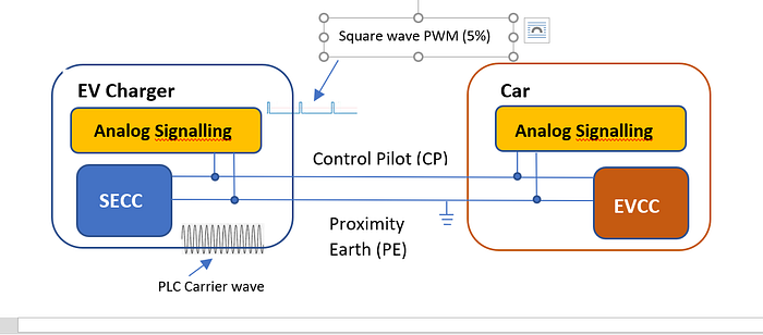
In HLC defined by ISO 15118, the communicating end point inside the EV Charger side is called Supply Equipment Communication Controller (SECC) and its counterpart inside the car is called Electric Vehicle Communication Controller (EVCC).
Communicating end points in HLC
So, although loosely saying that the EV Charger and the car participate in HLC is not incorrect, it would be technically accurate to say that the SECC (in the EV Charger) and the EVCC (in the car) participate in HLC.
Data communication model
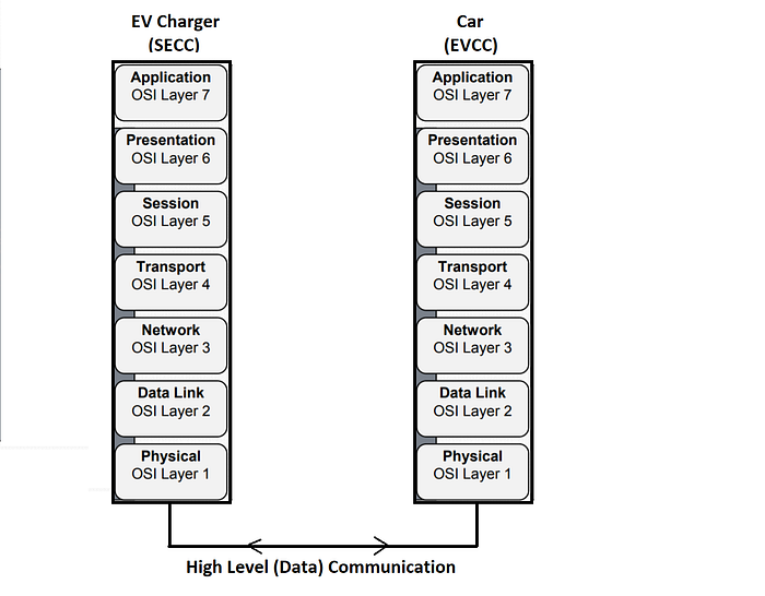
The SECC (in the EV Charger) and the EVCC (in the car) establish a data communication network by establishing the 7 functional layers as outlined in the well-established ISO/OSI data communication model. As per the model, each layer builds upon the functionality that is provided by the underlying layers, starting with the physical layer at the bottom all the way up to the application layer at the top.
ISO/OSI data communication model (Diagram courtesy: Tesla)
Layers 1 & 2
The physical and data link layers are implemented as per Part-3 of ISO 15118 using Power Line Communication (PLC), which typically uses a HomePlug Green PHY (IEEE1901) modem. At the physical layer (layer 1) the modems at both ends connect to the same physical line of the Control Pilot (CP), over which a high frequency carrier in the 1.8MHz to 30MHz range is transmitted. The carrier wave is modulated with the HLC message data packets, achieving a maximum data rate of 10Mbps.
The CP line, therefore, is multiplexed across the 2 modes of communication, as follows:
1) AS: +12V/-12V 1000Hz square wave (between the IEC 61851 compliant circuitry at both ends)
2) HLC: 1.8MHz to 30MHz PLC carrier wave, modulated with data message packets (between the SECC and EVCC as per ISO 15118)
The media access/data link layer (layer 2) is managed by the Signal Level Attenuation Characteristic (SLAC) protocol as defined by the HomePlug Green PHY v.1.1.1 specification. SLAC is designed for automotive applications, where multiple EVs could connected simultaneously to an EV Charger. The carrier signal’s attenuation level from each car is measured at the EV Charger during the Association Procedure in order to uniquely determine the identity of the cars. Security is optionally added using public key signature.
The layer 2 SLAC protocol stack is typically provided by HomePlug Green PHY compliant silicon vendors, like Qualcomm. SLAC sets up a reliable and secure frame transfer mechanism between the 2 nodes over the physical medium, guaranteeing error free transfers. During the SLAC initialization procedure, the PLC modem at the SECC (in the EV Charger) and EVCC (in the car) get unique MAC addresses. After the SLAC handshake is successful, the PLC modems at the SECC and the EVCC form a logical network.
Layers 3 & 4
The network layer (layer 3) is an IPv6 stack that layers over the MAC address. DHCP is used for host configuration and ICMPv6 sends network layer error messages. Each node, therefore, gets an IPv6 address. The transport layer (layer 4) stacks — TCP (reliable), UDP (fast), and optionally Transport Layer Security/TLS (safe) get layered on top of the IPv6 (layer3) stack. TCP provides flow control, congestion control and triggers retransmissions upon error conditions for guaranteed delivery.
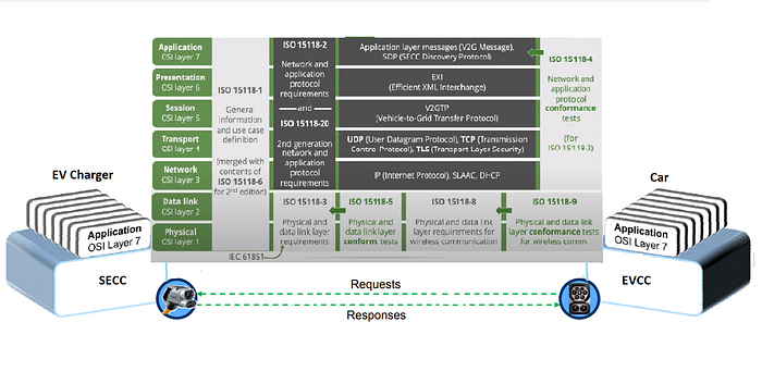
Applicability of the different Parts of ISO 15118 to the 7-layered V2G Protocol Stack (Diagram courtesy: Tesla, Switch)
Layers 5, 6 & 7
The V2G Transfer Protocol (V2GTP) is (layer 5/session) layered over the transport layer for session management between the EV Charger (also called “grid side” **) and the car. The presentation layer (layer 6) consists of encoding and decoding between application (XML) format and network Efficient XML Interchange (W3C EXI 1.0) format and negotiating/establishing an application layer protocol along with version number. The application (layer 7) V2G messages that have specific meanings in the context of the charging process/session are communicated between the SECC (in the EV Charger) and the EVCC (in the car) utilizing the completed layers of the underlying protocol stack. Domain Name Service (DNS) and SECC Discovery Protocol (SDP) protocols at layer 7 help resolve addresses and discover the SECC respectively. V2G stacks that implement layer 3 to layer 7 are available as open source as well as proprietary.
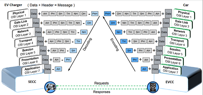
Data packet format, with layer-wise headers (Diagram courtesy: Tesla)
Like every layered communication model, each layer adds its own header to the original payload received from its upper layers during transmission. Vice versa during reception — each layer strips off its header before passing on the payload to its upper layers. Now, doesn’t the above description, layering and packet diagram look very familiar!
Before diving deeper into HLC, let us first examine how it is related to AS.
Close relationship — HLC and AS
The lifecycle of a charging session involving the EV Charger and the car consists of the following state sequences, that are managed together by AS and HLC.
· Unmated — EV not yet connected (State-A)
· Mated — EV detected, not ready to charge (State-B)
· Initialize — EV detected, ready to charge (State-C), Initialize HLC
· Cable check — Connector is locked on the car side for safe DC Charging
· Pre-charge — Adjust EV Charger’s output voltage to the car’s battery voltage
· Charge — Control actual power transfer
· Power down — EV still detected, but no longer ready to charge (State-B)
· Unmated — EV no longer connected (State-A)
IEC 61851 that defines AS describes different modes of charging, as follows with the last section in bold of special interest to us:
Charging Mode 1 — AC charging from mains over standard 1phase/3phase sockets. Up to 16 A and 250/480 V. No protection device in the charging cable.
Charging Mode 2 — AC charging from mains over standard 1phase/3phase sockets. Up to 32 A and 250/480 V. Protection device integrated in the charging cable.
Charging Mode 3 — AC charging using dedicated AC charging stations. Mandatory PWM signalling and optional High-Level Communication (HLC)
Charging Mode 4 — DC charging using dedicated DC charging stations. Mandatory PWM signalling and mandatory High-Level Communication (HLC)
We can see that mode 4 is the charging mode for DC charging from a DC Charging Station using mandatory AS and mandatory HLC.
IEC 61851 further classifies the Charging mode 4 (above) into 3 systems, as follows with the last section in bold of special interest to us.
System A — The physical/data layer is CAN bus A interface. The application layer is defined by IEC 61851–24. (This is used in CHAdeMO system)
System B — The physical/data layer is CAN bus B interface. The application layer is defined by the GB/T 27930 standard. (This is used in the Chinese system)
System C — The physical/data layer is Power Line Communication (PLC). The application layer is defined by the ISO 15118 protocol. (This is used in the CCS2 system)
We can see that in System C which has been adopted by the CCS2 system, ISO 15118 specifies the usage of Power Line Communication (PLC) for HLC. We can therefore think of IEC 61851 as the “mother” standard that defines the context and the need for ISO 15118 as the “daughter” standard. Needless to say that mother historically precedes daughter.
Initiating HLC
We saw in the previous (first) part how the AS session is initiated by electrically detecting the event of plugging in the car to the EV Charger. So how is the HLC session initiated? Well, it turns out that it is AS itself that initiates HLC! Let us see how.
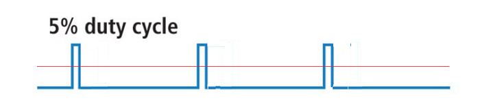
We had seen that the valid range of PWM duty cycle between the EV Charger and the car is between 10% and 96%. Why these figures, precisely? At 96% duty cycle, we hit the maximum current of 80A as defined by IEC 61851. And at 10%, we are at 6A which is the lowest current rating of any common domestic power outlet. That should have meant that any value of the duty cycle less than 10% (or greater than 96%) should have been invalid. But no! They chose a special value of 5% duty cycle for a very special purpose — to signal the need for HLC.
The 5% duty cycle waveform in AS, that triggers HLC
Hence if the duty cycle is set to 5% in AS, then it is an indication that additional HLC is required. In practice, there is a small tolerance around the 5%, so actual duty cycles could vary between 3% and 7%.
So, while the Control Pilot (CP) and Protective Earth (PE) lines of the EV Charger and the car are connected (mated), and when a 5% duty cycle square wave is detected, it causes the HomePlug Green PHY modems at the SECC (EV Charger) and the EVCC (car) to establish a physical link over the 1.8MHz-30MHz carrier wave signal, thereby establishing layer-1 of the HLC protocol. What an ingenious way to electrically initiate the transition to setup a data communication stack!
Just a trigger, not a participant
It may be worth clarifying here that although AS is responsible for triggering HLC by issuing the 5% duty cycle square waveform on the CP line, once HLC is established between the EV Charger and the car over PLC, AS has no role to play in the data communication session. Like a mother marrying off her daughter and letting her live by herself! This means that AS is totally transparent to the SECC and EVCC in the context of digital communication, and is separately handled by the EVSE controller (on the EV Charger) and the base controller (on the car), both of which implement the IEC 61851 protocol.
Multiplexing physical lines across AS and HLC modes
SECC (EV Charger) and EVCC (car) are involved only in HLC over PLC carrier wave. They are not involved in AS, although the same physical lines of CP and PE are shared between the 2 modes. Like the mother and the married daughter still share their family car for shopping together, but keep their bags separate! AS is handled through discrete voltage levels and square wave PWM by means of separate analogue circuitry on the EV Charger side (also called “grid side” **) and in the car, as per IEC 61851, as we saw in the previous (first) part of this article.
(**)”grid side” : Now we know why HLC is also commonly known as V2G (Vehicle-to-Grid), and in some instances V2H (Vehicle-to-Home). For the car, the EV Charger represents the front end to the home or/and the grid.
HLC architecture
HLC is a Client/Server protocol, where the EVCC (car) acts as the Client and the SECC (EV Charger) acts as the Server. It is based on a “request — response” mechanism as defined by Part-2 of ISO 15118, that defines a set of V2G request/response messages between the EVCC and the SECC. As per this mechanism, the car always sends request messages and the EV Charger sends back the corresponding response messages.
An example of a request — response message pair illustrating car-initiated V2G messages, is as follows:
The car sends this request message at the beginning of the charging session to find out the V2G protocol version supported by the EV Charger. All subsequent message exchange is possible only after the both handshake on the protocol version.
A few exceptional messages are triggered by the EV Charger, although not sent by it. As mentioned above, the EV Charger never directly sends a request message. In the exceptional cases, a message sequence is triggered indirectly by the EV Charger by setting a flag in its (previous) response message. The car responds to this by sending a new request message. Hence, request messages are always sent by the car. Renegotiation of the charging schedule when the grid undergoes unexpected demand fluctuations is an example of this exceptional case.
Message Timings
The car sends a new message every 60 seconds at the latest. The EV Charger must respond within 2 (to 5) seconds (depending on the message) to the incoming request. A few messages like CertificateInstall/Update and CableCheck have a larger timeout value.
V2G message sequences
The HLC model consists of various stages of the charging sequence as shown below, which also forms the basis of meaningful grouping V2G messages:
A. Start of charging process
B. Communication setup (meaning HLC)
C. Certificate handling
D. Identification and Authorization
E. Target setting and charge scheduling
F. Charge controlling and rescheduling
G. Value-added services
H. End of charging process
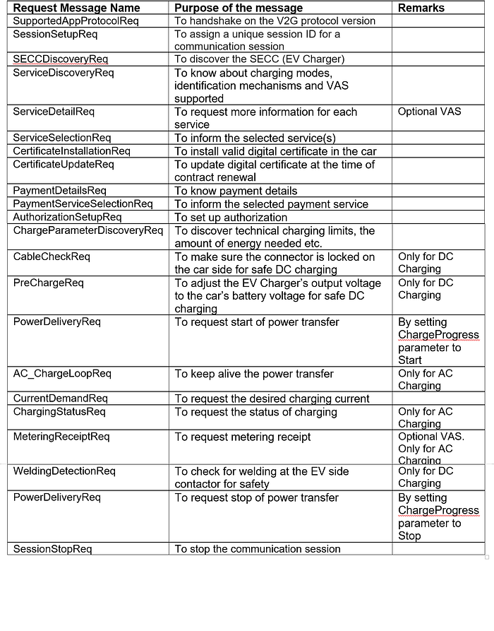
The following table describes V2G messages in more detail, though not exhaustively. The “Req” suffix indicates a request message sent by the car. There will be a corresponding “Res” response message sent by the EV Charger.
V2G message sequences in HLC
# From the EVEnergyRequest parameter of the ChargeParameterDiscoveryReq message, the EV Charger comes to know how much energy the car is requesting to transfer into the battery.
# From the optional EVRESSSOC parameter of the ChargeParameterDiscoveryReq message, the EV Charger learns the State of Charge (SoC) of the battery (in %).
# From the CurrentDemandReq message it knows how much charging current the (BMS of the) car is requesting.
# The user sets the departure time on the car’s dashboard. From the DepartureTime parameter of the ChargeParameterDiscoveryReq message, the EV Charger learns the time of departure desired by the user.
#From the TimeToFullSOC parameter of the ChargeParameterDiscoveryReq message, the EV Charger knows the remaining time to charge.
It looks like some light has started shedding on the basic questions that we set out with! Meanwhile, the optional nature of some of these parameters in ISO 15118 is driven by European GDPR regulations on how much information the user wants to share.
Industry trends
Many advanced features of EVSE-EV communications are getting incorporated into ISO 15118, and commercial products implementing these features are steadily hitting various global markets. Imagine the richness of features that we are going to witness in the near future in emerging economies like India, as EVSE-EV communication tries to cover new scenarios, such as:
Plug & Charge — Just plug in the car, and the EV Charger recognizes the owner! No more RFID, QR code, mobile App etc.
Smart Charging — Synchronize with the grid through EV Chargers on charging schedules and charging currents of cars based on overall loading conditions of the grid, like charging at off-peak hours
Demand-based responsiveness — Dynamically synchronize through EV Chargers the charging of millions of EVs, especially at the time of unforeseen grid power fluctuations to avoid overwhelming the historically shaky grid capacity
We test our EV Charger designs using a Battery Communications Simulator. The Simulator works exactly like a car, providing the same connector pins that work on AS as defined by IEC 61851 and capable of the HLC as defined by ISO 15118. Such is the beauty of standardization that compliance during design ensures that the EV Charger will work correctly when deployed in the field with any compliant car model (mechanically, electrically, communication-wise and software-wise).
Specifically, Part-20 of ISO 15118 that was released last year (2022) includes certain futuristic features such as:
Bidirectional Power Transfer (BPT) — Feeding the car battery’s power back to the home, or into the grid. Imagine charging the car at off-peak hours and feeding power back (selling) to grid at peak-hours (at better rates)!
Wireless Power Transfer (WPT) — Zero contact for power transfer while charging your car! Also called inductive charging, the transmitter coils (source) are encased in a plate embedded on the ground, for instance at a car parking. The receiver coils (load) are installed in the car conveniently close to the battery, which is anyway located at the floor of the chassis in most EV designs. So, one needs to just position the car using the guidance markings, so that the pair of coils align properly and charge by inductive coupling.
Automated Connection Device (ACD) — Space-age robotic arms that would avoid the manual operation of plugging in the charging gun to the charging inlet of the car. Pantographs are already popular with bus fleets. This would be useful especially for heavy water-cooled cables of Ultra-fast Chargers, and for autonomous vehicles. Imagine the irony of having to manually charge a driverless car!
Conclusion
From the above concentrate of the wide spectrum of EV Charging standards juice, we can see that AS and HLC combine symbiotically to establish a complete e-Mobility communication system for EV Charging. So, the next time you plug in your electric car to an EV Charger, you will know better that it’s not just all voltages and currents. The software engineer in you can now visualize the 7-layer protocol stacks being loaded at both ends of that cable and V2G message sequences going back and forth even before power starts flowing into your car battery. You will probably smile knowing that the cable that is electrically charging your car is also buzzing with V2G activity literally all the time!
About the author
Ram Mohan Ramakrishnan
Principal Consultant, Automotive
NeST Digital
That the contents of third-party articles/blogs published here on the website, and the interpretation of all information in the article/blogs such as data, maps, numbers, opinions etc. displayed in the article/blogs and views or the opinions expressed within the content are solely of the author's; and do not reflect the opinions and beliefs of NASSCOM or its affiliates in any manner. NASSCOM does not take any liability w.r.t. content in any manner and will not be liable in any manner whatsoever for any kind of liability arising out of any act, error or omission. The contents of third-party article/blogs published, are provided solely as convenience; and the presence of these articles/blogs should not, under any circumstances, be considered as an endorsement of the contents by NASSCOM in any manner; and if you chose to access these articles/blogs , you do so at your own risk.
NeST Digital, the software arm of the NeST Group, has been transforming businesses, providing customized and innovative software solutions and services for customers across the globe. A leader in providing end-to-end solutions under one roof, covering contract manufacturing and product engineering services, NeST has 25 years of proven experience in delivering industry-specific engineering and technology solutions for customers, ranging from SMBs to Fortune 500 enterprises, focusing on Transportation, Aerospace, Defense, Healthcare, Power, Industrial, GIS, and BFSI domains.
The mobility industry, encompassing vehicles moving on land, air and water, is undergoing a digital transformation fueled by automation technology disruptions occurring at a rapid pace. The quantum of change expected in the next decade would be much…
We are on the verge of an engineering revolution that could change the way we live forever. There will be a huge economic impact as we move towards a world powered by renewables. But it is not just about economics - it is also about the environment…
While investment and sustainability might seem like two entirely opposite aspects, the recent climate trends have forced them to collide. Often the process of making investment concerns vetting a company based on factors including business model,…
As the state of the climate remains ever-worsening, and it continues to become increasingly evident that climate change is a problem we cannot hide from, many turn their heads towards large corporations and their hand in this. While many have…
Hospitals depend on energy to run their services, operate critical equipment and save lives. It's a vital operation but also an expensive one.
In England, the NHS spends £500 million a year on energy1 – making healthcare one of the nation's highest…
Latin America to see most of the offshore oil and gas growth during 2021-25
Latin America will be the most promising region for offshore oil and gas development by 2025. The lower breakeven prices in the region make the offshore projects in the…